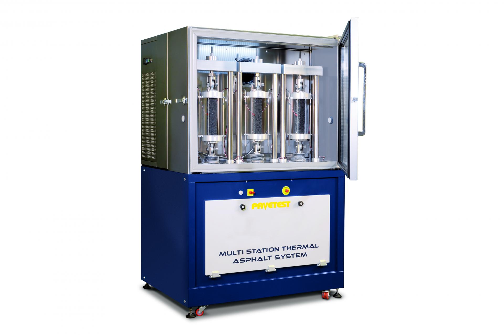
THE NEXT GENERATION OF MULTI-STATION THERMAL ASPHALT SYSTEM
The Thermal Stress Restrained Specimen Test (TSRST) is used to determine the low-temperature cracking susceptibility of asphalt concrete. In the early 1990s, the TSRST was developed by Oregon State University (OSU) as part of the Strategic Highway Research Program. The test method became AASHTO TP10.
Main Features
- Up to three working stations (electromechanical and/or servo-hydraulic stations).
- Servo-hydraulic actuator: 30 kN static, 25 kN dynamic, double acting, fatigue rated and equal area type with long-life Labyrinth bearings & seals.
- DynafloTM Hydraulic Power Supply: Variable Frequency Drive 2.2 kW pump motor; Silent operation.
- Ability to clone, modify and/or generate users’ method file(s) to suit their specific requirements.
- A programmable test Wizard will guide the operator step by step based on a recipe book approach.
- The temperature controller is programmed via PC software.
The basic MULTI TSRST includes the main frame, the CDAS2, the climatic chamber, the refrigeration unit and at least one between the electro-mechanical or servo-hydraulic station. Here are the available configurations:
- B282-10: 1 electromechanical station
- B282-11: 2 electromechanical station
- B282-12*: 3 electromechanical stations
- B282-13: 1 servo-hydraulic station
- B282-14: 1 electromechanical station / 1 servo-hydraulic station
- B282-15*: 2 electromechanical stations / 1 servo-hydraulic station
NOTE: Multiple station configurations (B282-11, B282-12, B282-14, B282-15) allow TSRST tests to be run simultaneously with all stations.
In this configuration, UTST, RT, TCT, UTSST and UTCST tests are performed on one station at a time. With a combined configuration (electromechanical and servo-hydraulic), UTCST must be performed with a servo-hydraulic station.
*NOTE: Compliant with AASHTO TP10, if using only one station.